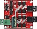
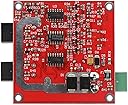
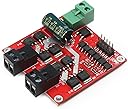
🚀 Drive Innovation Forward with Power and Precision!
The DROK DC Motor Driver L298 Dual H Bridge is a compact, high-performance motor controller designed for professional-grade projects. It supports a wide input voltage range of 6.5V to 27V, delivers a robust 7A output current per motor port, and can handle up to 160W total power. Featuring dual H-bridge architecture, it independently controls two DC motors with forward and reverse rotation capabilities. PWM input enables precise speed regulation up to 10kHz, while built-in under voltage protection ensures durability and reliability. Ideal for millennial professionals seeking efficient, versatile motor control solutions in compact form.


| ASIN | B06XGD5SCB |
| Best Sellers Rank | 309,746 in Business, Industry & Science ( See Top 100 in Business, Industry & Science ) 1,469 in Motor Speed Controllers |
| Brand | DROK |
| Colour | Red |
| Customer Reviews | 4.4 out of 5 stars 188 Reviews |
| Item Dimensions L x W x H | 5.5L x 5.5W x 1.6H centimetres |
| Manufacturer | DROK |
| Manufacturer Part Number | 200206 |
| Material | Metal |
| Model Number | 200206_OZ |
| Number of Items | 1 |
| Product dimensions | 5.5L x 5.5W x 1.6H centimetres |
| UPC | 701822755689 |
C**L
Puissance de sortie et rendement
Je mets l'accent sur la puissance de sortie car celle proposée par exemple par les modules L298 limitent la sortie à 2A alors que là avec 7A on fait face à la plupart des applications. Pilotage indépendant de 2 moteurs dans les 2 sens avec entrées PWM pour la variation de vitesse. Je l'emploie avec un Arduino UNO. Le variation de vitesse va de 0 à 100% (je dis bien 100% plus de découpage mais tension maximale). Pour la sécurité en cas de coupure d'alimentation alors que les moteurs sont à pleine vitesse le fabriquant conseille l'utilisation d'un relais pour protéger le dispositif de l'effet dynamo des moteurs qui induirait des tensions inverses sur les transistors à effet de champs (puisque plus alimenté par la coupure d'alimentation), moi j'ai mis un pont redresseur sur le moteur (entrées alternatives sur les bornes du moteur, la sortie plus vers le plus de l'alimentation et la sortie moins vers ... le moins (vous l'aurez deviné). La tension inverse reçue par les transistors est au maximum de 0,6V ce qu'ils supportent sans problème.
M**D
Fonctionne super bien
Super, marche très bien!
G**N
Flawless performance. Highly recommended! Here's some help getting started
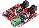
This unit is perfect for my application with a couple of 2-3 amp DC motors and worth far more than the cost. I require frequent direction changes and large starting current spikes, but the board stays cool and doesn't need heat sinks. The connectors have screw terminals and removable snap lock connectors which are excellent. The documentation looks great on glossy paper but needs some clarification. Here's a few tips and a Arduino test setup: 1) This double H-bridge can run two motors independently of each other. 2) Each motor can run forward, reverse, brake, full speed forward, and full speed reverse. 3) Categories of inputs (you provide these) to the board are: a) Main power (up to 15 amps) that is used to drive both motors. Read the instructions around voltages, current, peak current, fuses, etc... b) Control logic for Motor A c) Control logic for Motor B d) 5v power you provide into the board for it's logic processing, etc.. with very little current draw. 4) For the main power input, you need a capable power supply. I'm using a 10amp battery charger. 5) You must feed 5v into the board. The board has 5v (and ground) pins for each motor, but you only need to provide 5v and ground on one set of pins. 6) Each motor needs three 5v logic inputs. For motor #1 they are labeled IN1, IN2, and ENA1. 7) The two pins labeled IN1 and IN2 are fed from any two GPIO(Arduino) pins with HIGH or LOW to control the mode of the motor such as forward, reverse and brake. See the control logic table in the instructions. 8) The pin labeled ENA1 REQUIRES!!! a PWM output from Arudino. You MUST NOT apply a steady voltage from something like a potentiometer or DAC output. 9) Here's a basic test setup for Arduino UNO if you need it: Connect 5v and ground to H-bridge, Connect main power Connect motor(s), you just need motor A for this test Connect Ardunio pin2 -> H-bridge pin IN1 Connect Ardunio pin3 -> H-bridge pin ENA Connect Ardunio pin4 -> H-bridge pin IN2 Create a test sketch as follows: void setup() { pinMode(2, OUTPUT); pinMode(3, OUTPUT); pinMode(4, OUTPUT); } void loop() { digitalWrite(2, LOW); //forward digitalWrite(4, HIGH); //forward analogWrite(3, 178); //pin 3 is PWM, 178/255 = (about) 70% speed. Max is 255. delay(1500); digitalWrite(2, HIGH); //reverse digitalWrite(4, LOW); //reverse analogWrite(3, 76); //pin 3 is PWM, 76/255 = (about) 30% speed. Max is 255. delay(3000); } Hope this helps get you started.
J**L
It works and it's perfect.
The chip didn't come in a box so the I/O pins got bent during the shipping. Aside from that, instructions are clear and got it to work within half an hour. I'm so happy with my purchase that I'm buying another one.
J**O
Helped replace a $500 Motherboard!
So the motherboard for my Apollo 835 Dual Swing Gate finally kicked the bucket after 20 years. While a replacement motherboard for my gate model was available for purchase, they were charging 500 bucks for it (and I was pretty sure I could do it for 50 bucks or less) The actuators that came with the dual swing gate kit operated at 12 volts with a fuse on the board limiting them to 3 amps. This made this dual L298 motor driver perfect in my quest to replace the motherboard. This dual L298 configuration has a similar pinout to just a single L298 board, except there are two of them. It still requires 12 volts to run the motor and a separate 5 volt to power the L298. The 5-volt pins for the L298 are connected so you only need a single pair of power cables. After writing some code for an Arduino Nano to mimic the original motherboard operation and rewiring each Swing gate actuator to work with the Nano and this motor driver. I was able to successfully replace the motherboard with about 20 dollars worth of new parts. A 3 Amp fuse is placed in series between the motor and the motor driver to prevent the motors from being damaged or if an object interferes when the gate is opening or closing. The motors don't have too much torque behind them, and the gates aren't heavy to move. While its current installation isn't pretty lol, it does not rain a lot where I am, and it also sits inside a weather-resistant metal box. I haven't had any issues for the past 3 mo since I installed this. (other than updating the programming on the Nano to fix some kinks) 11/10 saved 470 bucks.
Trustpilot
3 weeks ago
2 weeks ago