Desert Online General Trading LLC
Dubai, United Arab Emirates
Desert Online General Trading LLC
Dubai, United Arab Emirates


🔧 Power Meets Precision - Elevate Your Control Game!
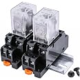
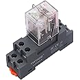
The TWTADE/DC 24V Relay is a high-performance electromagnetic relay designed for professional applications. With a robust 10A contact capacity and a smart indicator light, this relay ensures reliable operation and easy monitoring. Its compact size and versatile DPDT configuration make it ideal for various wiring setups, while the included socket and base hook simplify installation on a 35mm DIN rail.


R**G
Simple, straitforward, DIN Rail for PLC box mounting, replaceable relay
I have purchased a number of these in days past. I cannot speak to their durability as I have yet to push them to their limits. But they are simple enough to install and operate. I have purchased this one specifically to match the rest and for a lower coil voltage. They always include a chunk of aluminum DIN rail for mounting. If you know the relay type it's simple enough to swap with a new one. Though I end up buying the whole assembly. Note: the safety strap can be a bit of a nuisance to replace after relay swap.
A**R
good product, worthwhile.
Nice and compact. Has a red LED which shows when the coil is activated. Nice feature.I used it to connect to my Blink doorbell camera to a large, mechanical chime which was otherwise incompatible with the door chime.
G**N
Works As Intended
I used this to control a remote well pump. The 24VAC signal from my sprinkler system controls this relay, which in turn opens and closes a contact which sends a WiFi signal to turn on the pump. No problems so far.
B**T
First one bad. Replacement was good.
First relay base sent had an open in it. Amazon shipped replacement within 2 days. It worked perfectly.
R**E
Does what it's supposed to, but lack of documentation is annoying
Relays in general can be confusing, but relays with no documentation just make it worse.While this appears to be made well and worked for what I bought it for, it sure was annoying having to puzzle through the terminals to figure out what's what. These don't appear to follow either NEMA or IEC relay numbering standards, and without instructions, you're on your own to test out the terminals. Thankfully the base is clearly marked, so that helped. My relay was supposedly a "24vac relay" but it appears to activate with either AC or DC power, I tried both successfully at 24 volts.If it helps anyone, here's the breakdown of an 8-pin:Pins 7 & 8 are your coil terminals, which activate the relay when power is applied to them. If AC is being used to activate the relay it doesn't matter, but if DC is activating the coil then pole 7 is negative and 8 is positive.Pins 1, 3, and 5 work together as a circuit.Pins 2, 4, and 6 work together as a circuit.The above is what makes this a "Dual Pole" (DP) relay - there are two independent poles where 1/3/5 (the terminals making up pole 1) do not touch terminals 2/4/6 (pole 2). You could use those two poles independently, such as to power two different devices requiring two different voltages, or you could use one pole as a power supply and the other as as a ground. There's a lot of options.Using just one pole as example, this is how the terminals can work:Pin 5 is incoming power that will be delivered to either pin 1 or pin 3, depending on if the relay is activated or not. It's labeled as "COM" because pins 1 and 3 have pin 5 in common.Pin 3 is "Normally Open", which means that when the relay is off/deactivated, there won't be any power supplied to pin 3 from pin 5. Power will only be applied to pin 3 when the relay is activated.Pin 1 is "Normally Closed" and works opposite of pin 3. When the relay is off/deactivated, there WILL be power supplied to pin 1 from pin 5. When the relay is activated, there will be no power to pin 1.Because the 1/3/5 circuit makes one circuit when it's powered and another when it's powered off, it's called a "Dual Throw" (DT).Combined together, this is a DPDT relay.Pins 2, 4, 6 work the same as the above.In my case, this relay was used to power a 120v outlet used to activate an outdoor fountain. A diagram is attached with details. I needed to be able to turn on this fountain two ways - either on a schedule from my smart home devices, or else manually via a hardware switch at the fountain. By utilizing the Dual Throw feature of the relay, I was able to accomplish this - when the relay is deactivated/off, power is supplied to the manual switch. When the relay is activated, power is killed to the manual switch.
M**N
Clarification of Pinouts and Usage
Item model number : 2PCS YJ2N-LY AC 110VDate First Available : March 21, 2022Manufacturer : TWTADEASIN : B09W251GXZRelay : YJ2N-LY, 110 VAC, Red LEDSocket : YJTF08A-E, 8-pin, 12A, 400 VThe diagram represents the above-stated relay’s pinouts. The relay is a DPDT device (double pole or two-commons or two-separate circuits; and double throw or two-contacts-per pole where one set of contacts is N.C. and the other N.O.). The power coil is an electromagnet that is activated by an A/C current. The electromagnet mechanically swings two separate arms that disconnects/connects internal relay contacts.One circuit is composed of pins #5 (common), #1 (N.C.) and #3 (N.O.).The other circuit is composed of pins #6 (common), #2 (N.C.) and #4 (N.O.).The A/C power coil is energized when A/C power is applied to pins #7 and #8.The circuits are separate with no electrical connectivity as shipped even though both circuits are controlled by one power coil.When A/C power is OFF and the power coil is not energized:- common #5 is connected or Normally Closed to pin #1 and there should be continuity between pins #5 and #1 (N.C.); there should be no continuity between pins #5 and #3 or Normally Open (N.O.)- common #6 is connected or Normally Closed to pin #2 and there should be continuity between pins #6 and #2 (N.C.); there should be no continuity betweens pins #6 and #4 or Normally Open (N.O.)When the power coil is energized with 110 VAC power:- common #5 disconnects from pin #1 and there should be no continuity between pins #5 and #1; at the same time, common #5 connects to pin #3 and there should be continuity between pins #5 and #3- common #6 disconnects from pin #2 and there should be no continuity between pins #6 and #2; at the same time, common #6 connects to pin #4 and there should be continuity between pins #6 and #4I hope this clarifies seemingly conflicting information submitted in some reviews.
Trustpilot
1 month ago
4 days ago
![Electromagnetic Power Relay, 8-Pin 10 AMP 24V DC Relay Coil with Socket Base, LED Indicator, DPDT 2NO 2NC - MY5NJ 2PCS [Applicable for DIN Rail System]](https://images-na.ssl-images-amazon.com/images/I/71StC62-2wL._AC_UL116_SR116,116_.jpg)